
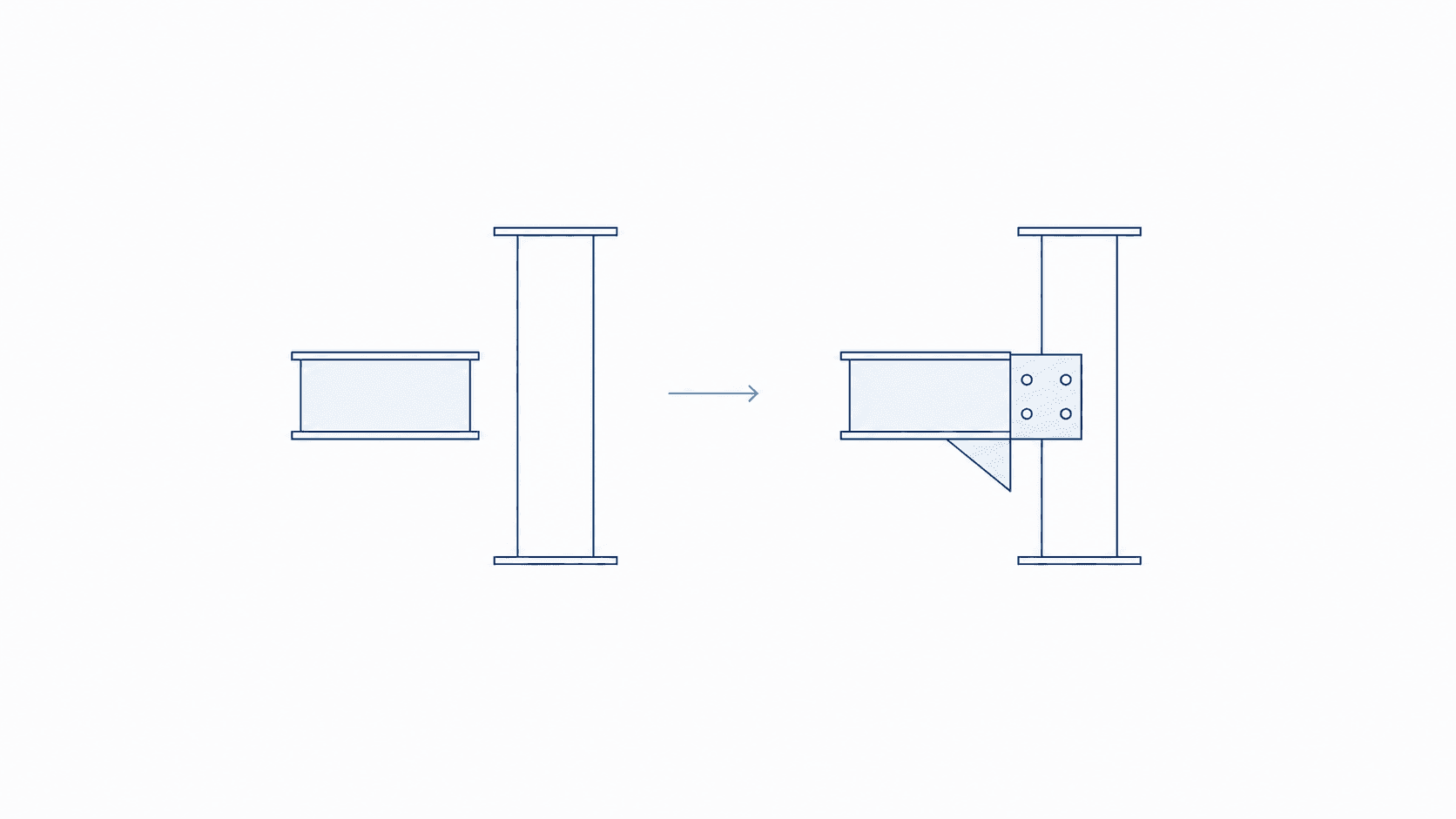
A coordinated building information model can pass clash detection and still be unsuitable for fabrication. This is not necessarily a failure of coordination. It is usually a sign that the project has treated coordination approval and fabrication release as the same decision.
They answer different questions.
Coordination asks whether architectural, structural and building-services systems can occupy the available space without unacceptable conflicts. Fabrication asks whether a trade contractor has enough verified information to select, order, manufacture, assemble and install the actual components.
When this distinction is not made clear, the gap appears later as site queries, revised shop drawings, aborted work, material changes or components that must be modified after production.
What a Coordinated Model Confirms
A coordinated model brings the relevant disciplines together so that interfaces can be reviewed before work reaches site. Depending on the agreed scope, it may include accurate system routes, principal equipment, fittings, access zones, openings, supports and connections to adjacent elements.
This level of development is valuable because it allows the project team to assess questions such as:
- Do the systems fit within the available ceiling or riser space?
- Are major elements clear of the structure and architecture?
- Can equipment be accessed for installation and maintenance?
- Are required penetrations identified and coordinated?
- Do drawings and model geometry describe the same arrangement?
In many BIM frameworks, teams associate this coordination stage with LOD 350. However, an LOD label should never replace a project-specific definition. The parties must still agree which elements, properties, tolerances and interfaces are included in each model package.
Fabrication Requires a Different Standard
Fabrication-ready information must support real production and installation decisions. Generic geometry that was adequate for spatial coordination may need to be replaced with selected products and actual assembly details.
The required information may include:
- confirmed manufacturer components and available sizes;
- final connection, joint and fitting geometry;
- supports, hangers, frames and fixing arrangements;
- approved builders’ work openings and penetration details;
- insulation, access and installation clearances;
- dimensions and tolerances appropriate to the assembly;
- spool, assembly or shop-drawing references;
- material, classification and specification information; and
- coordinated revisions that match the issued fabrication documents.
The exact requirements vary by trade, procurement route and contract. Ductwork, pipework, reinforcement, structural steel and prefabricated service modules do not reach fabrication readiness through an identical checklist.
This is why a model described as LOD 400 should not be accepted based on visual detail alone. The team must confirm that its geometry and information are suitable for the defined fabrication purpose.
The Risk Sits at the Handoff
The transition from multidisciplinary coordination to trade fabrication often crosses organisational and contractual boundaries. A consultant may issue design intent, a main contractor may manage the coordinated model, and specialist subcontractors may develop the final production information.
At this point, assumptions can replace clear responsibility. One party believes a connection has been resolved because the model is clash-free. Another assumes the model contains approved products and installation tolerances. A release date arrives, but nobody has confirmed that the package has earned fabrication status.
The answer is not simply more clash detection. The handoff needs a controlled release process with defined inputs, checks, responsibilities and approval records.
Treat Fabrication Release as a Quality Gate
Fabrication release should be a verified state, not only a programme milestone. Each package should pass a set of checks appropriate to its trade and intended use before information is issued for production.
| Release check | Risk it helps control |
|---|---|
| Selected products and fittings are confirmed | Specifying components that are unavailable or incompatible |
| Supports, hangers and secondary steel are included | Late clashes caused by unmodelled support systems |
| Openings and penetrations are approved | Site cutting or drilling that conflicts with structural requirements |
| Access and installation clearances are verified | Coordinated geometry that cannot be installed or maintained |
| Assembly tolerances are defined | Model dimensions being interpreted as exact installation instructions |
| Model, shop drawings and schedules agree | Fabrication from documents based on different revisions |
| Required data and references are complete | Components arriving without traceable specification or asset information |
| Package approval and revision are recorded | Uncertainty over what was authorised for production |
The checklist should be proportionate. Its purpose is not to add administration; it is to make the release decision visible and repeatable.
Coordinate, Verify, Release
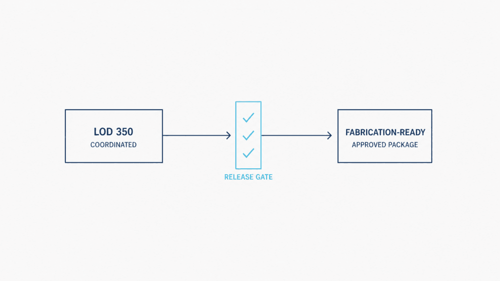
A practical workflow can be organised into three stages:
1. Coordinate
Federate the relevant discipline and trade models. Resolve spatial conflicts, confirm interfaces and protect access, clearance and installation zones. Record outstanding decisions instead of hiding them to achieve a nominal clash-free status.
2. Verify
Review the package against its agreed fabrication requirements. Confirm the selected components, connections, supports, openings, tolerances, data and document alignment. Assign each check to a named responsible party and close it with evidence.
3. Release
Issue only the verified package for production. Record its status, revision, approval and relationship to the accompanying shop drawings or schedules. Any later change should follow an agreed change-control process so that the fabrication team is not working from superseded information.
Name the Release Owner
A quality gate is effective only when someone has authority to stop a package that is not ready.
The release owner may be the BIM manager, digital-delivery lead, design manager, construction manager or another role defined by the project’s responsibility matrix. The title matters less than the authority and accountability attached to it.
The project should establish:
- who prepares the fabrication package;
- who reviews each technical interface;
- who verifies information completeness;
- who approves openings and structural implications;
- who authorises the final release; and
- how the decision is recorded in the common data environment.
Responsibility should be agreed before the first package reaches the gate. Assigning ownership after a fabrication issue has occurred is too late.
Define LOD Through Deliverables
LOD terminology can support communication, but it should not be the only description of a model requirement. Different teams may interpret the same number differently.
A stronger requirement combines the intended use with specific deliverables and acceptance criteria. For example, instead of requesting only an “LOD 400 model”, the project can define:
- the systems and elements included;
- the required geometric detail;
- the properties and classifications to be provided;
- the drawings, schedules or spool outputs expected;
- the coordination and approval dependencies;
- the tolerance rules; and
- the evidence required for release.
This gives consultants, contractors and fabricators a shared definition of completion and makes model review more objective.
Better Handoffs Reduce Site Uncertainty
The progression from coordinated design to fabrication is not a simple increase in model detail. It is a managed transfer of responsibility from spatial coordination to production information.
Projects reduce risk when they separate these approvals, define what fabrication readiness means for each trade and require every package to pass a controlled release gate. The result is a clearer audit trail, better alignment between models and shop drawings, and fewer assumptions reaching the site team.
A coordinated model confirms that the proposed systems can work together. A fabrication-ready package confirms that a defined assembly can be produced and installed from the issued information. Successful BIM delivery depends on knowing which of those decisions the project has actually made.